The IO/LED Devices category permits custom control of the general purpose I/O and LED devices. The serial (COM) port and parallel (LPT/printer) ports come standard on most computers, while the other items are general purpose I/O boards. Some of the available devices have both digital I/O and analog output pins. Digital Input pins may be used to capture events. Use the following steps to add a IO/LED Device to a profile and test it:
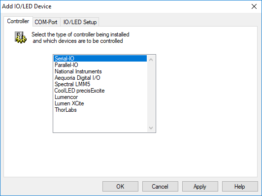
Select the IO/LED Controller type to add to the Profile. Install the manufacturer drivers if necessary.

Select the LPT port for parallel communications. The port address must be correctly set to achieve proper control. The default values are likely to be correct, but may not be in all cases. The parallel port must be set in SPP mode. Click in the address field to edit the address.
Depending on the specific device, it may have a number of input lines and a number of output lines.
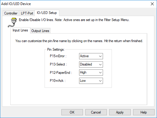
The pin names may be customized, e.g., to reflect the purpose of the signal they are sensing. This can make future interactions within the software involving the device more intuitive. Digital output lines have a similar interface. In addition, combinations of output values on the available pins can be configured and assigned names which will then be available.
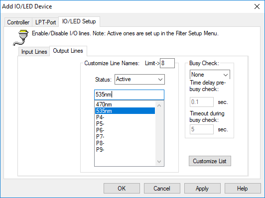
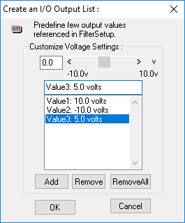
Analog output lines on some I/O cards have additional settings permitting control over the range of output voltages which will be produced.
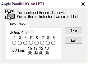
Once I/O communication has been configured in the Profile, press Apply to verify your device in the Apply Dialog. Pressing the Test button will perform a scan of each of the active input pins and a double- toggle (on / off) of each of the output pin's states to provide a convenient means to verify the I/O device's configuration.
